
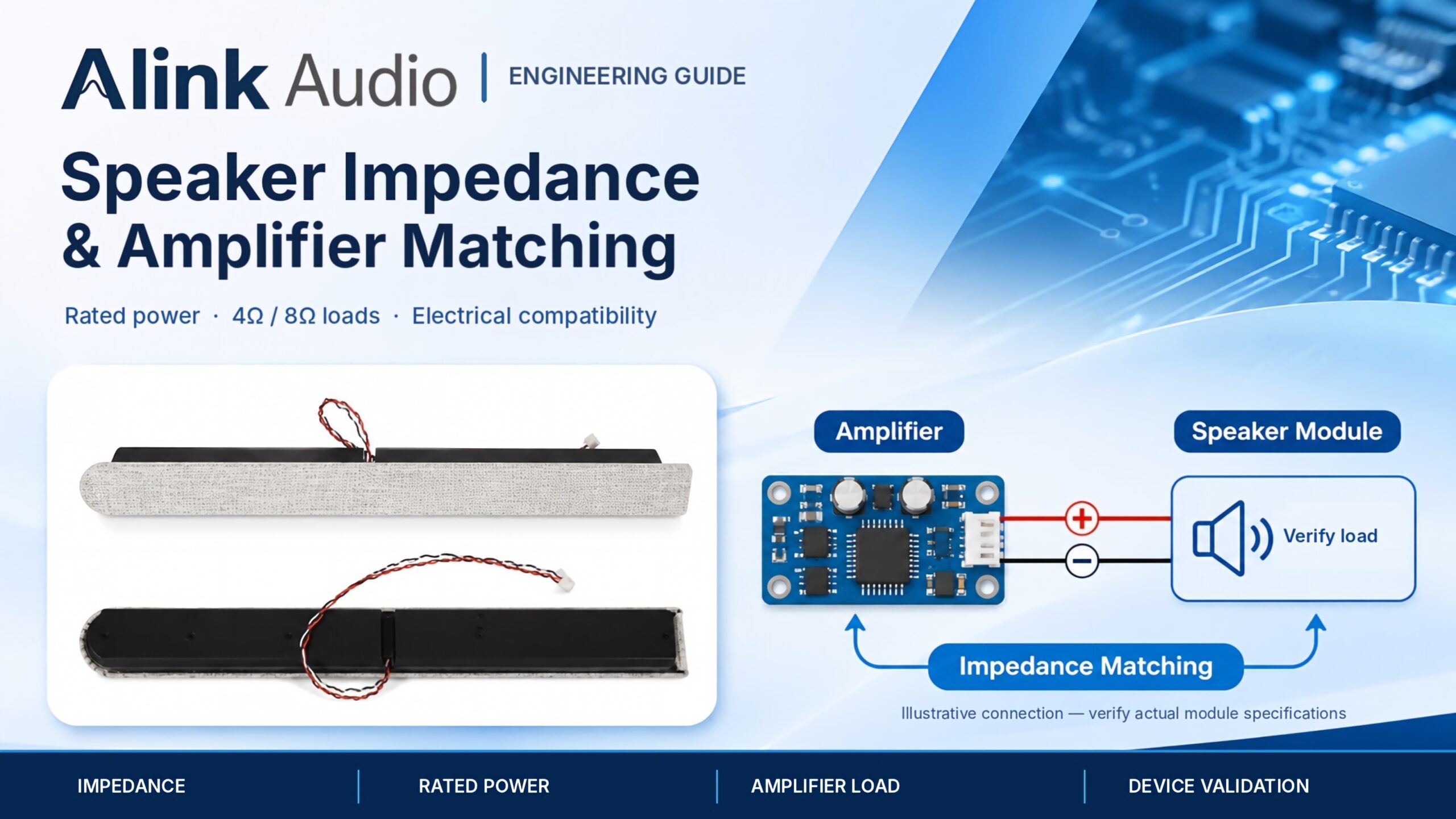
Why can the same amplifier deliver different output power when connected to a 4 Ω speaker module instead of an 8 Ω module? And does a speaker rated at a higher wattage necessarily produce more sound?
These are common questions when engineers select audio components for security devices, commercial displays, smart terminals, and other OEM/ODM electronic products.
Speaker impedance and rated power are important, but they do not independently determine whether an amplifier and speaker module are compatible. Engineers also need to consider the amplifier’s supported load, supply voltage, output configuration, distortion limits, and the acoustic requirements of the finished device.
A practical matching process starts with confirmed electrical specifications and ends with testing under representative operating conditions.
If you are still deciding which module type suits your equipment, see our guide to choosing an embedded audio module before comparing electrical configurations.
1. What Does Speaker Nominal Impedance Actually Mean?
Nominal impedance describes a speaker’s specified electrical load, commonly expressed in ohms (Ω).
Embedded speaker modules are often available in configurations such as 4 Ω or 8 Ω, although other values and multi-circuit arrangements may also be used.
However, nominal impedance is not a fixed resistance measured at every frequency.
A speaker is an electromechanical device, and its electrical impedance varies with frequency. The impedance curve may include a resonance peak and other changes related to the driver and its acoustic system.
For preliminary selection, nominal impedance helps engineers understand the intended load category. For detailed amplifier evaluation, the actual impedance behavior and the amplifier’s operating limits may require further review.
Is a 4 Ω Speaker Better Than an 8 Ω Speaker?
Neither option is automatically better.
A 4 Ω module can draw more current than an 8 Ω module at the same applied voltage, assuming a simplified resistive-load comparison. Whether that produces useful additional acoustic output depends on the amplifier and speaker characteristics.
An 8 Ω module can reduce current demand under the same voltage conditions, but the available output power may also differ.
The suitable choice depends on the required output level, amplifier capability, supply conditions, thermal design, and device constraints.
What If a Module Is Specified as 8 Ω + 8 Ω?
Some speaker assemblies contain multiple drivers or independent electrical circuits.
A specification such as 8 Ω + 8 Ω should not automatically be simplified to a single 8 Ω load.
Engineers must confirm the number of circuits, wiring arrangement, and intended amplifier channels before determining the electrical load.
Engineering Takeaway: Use nominal impedance for initial selection, but confirm the complete circuit configuration and amplifier load requirements before approving a module.
2. How Do 4 Ω and 8 Ω Speaker Loads Affect Output Power?
The relationship between voltage, current, resistance, and power helps explain why load impedance matters.
For an ideal resistive load, two simplified equations are:
Current = RMS Voltage / Resistance
Power = RMS Voltage² / Resistance
These equations are useful for illustrating electrical behavior. Actual loudspeakers have frequency-dependent impedance, and real amplifiers have voltage, current, distortion, and thermal limitations.
A Simplified Electrical Comparison
Assume an ideal amplifier maintains the same 2 V RMS output across either resistive load.
| Electrical Parameter | 4 Ω Load | 8 Ω Load |
|---|---|---|
| Applied RMS Voltage | 2 V | 2 V |
| Calculated RMS Current | 0.50 A | 0.25 A |
| Calculated Load Power | 1.0 W | 0.5 W |
| Practical Consideration | Higher current demand | Lower current demand |
Illustrative calculation only. This is not measured performance data from an Alink Audio module or a specific amplifier.
The example shows that reducing load resistance increases current demand when the same RMS voltage is maintained.
However, a real amplifier may not maintain the same voltage under every load. Its current limit, power supply, thermal protection, and output configuration can change the result.
Does More Electrical Power Mean More Acoustic Output?
Not automatically.
Speaker sensitivity, frequency response, enclosure design, installation conditions, and signal content also influence the sound produced.
Two different speaker modules receiving the same electrical power may deliver different sound pressure levels.
Engineering Takeaway: Compare amplifier capability and acoustic requirements together. Do not assume that lower impedance or higher electrical power automatically produces better sound.
3. What Is the Difference Between Rated Power and Maximum Power?
Rated power and maximum power are often confused during speaker module selection.
Rated power refers to a specified power-handling capability under defined conditions. Its meaning should be checked against the manufacturer’s stated test method and rating criteria.
Maximum power may describe a different short-duration or test-specific limit. It should not automatically be treated as a continuous operating target.
For example, if a product specification contains both rated power and maximum power, those figures should be interpreted according to the documented conditions rather than treated as interchangeable values.
The same principle applies to amplifier specifications.
An amplifier’s advertised output power may have been measured under a particular load impedance, supply voltage, frequency, and distortion threshold.
Should Speaker Rated Power Equal Amplifier Output Power?
Not necessarily.
A numerical match between speaker rated power and amplifier output power does not, by itself, establish a safe or effective design.
Engineers should evaluate the expected operating signal, output limits, protection strategy, thermal conditions, and the speaker’s documented capabilities.
An amplifier capable of delivering more power than the speaker’s rating may still be usable if the system is designed and validated to keep actual drive conditions within appropriate limits.
Likewise, an amplifier with a lower advertised wattage is not automatically safe under every operating condition.
Engineering Takeaway: Compare ratings only when their test conditions and meanings are understood. Define acceptable operating limits for the complete system.
4. Why Can Amplifier Power Ratings Be Misleading?
Two amplifiers advertised with similar wattage figures may behave differently in the same device.
Before comparing specifications, review the conditions used to obtain the published output power.
Important factors include:
- Supply voltage.
- Speaker load impedance.
- Output configuration.
- Measurement frequency or bandwidth.
- Total harmonic distortion and noise (THD+N).
- Continuous or short-duration operating conditions.
- Current limiting and thermal protection.
Why Does THD+N Matter?
Amplifier output power is sometimes specified at different distortion levels.
A power figure measured at a higher distortion threshold may not represent the output level acceptable for a particular voice or multimedia application.
Engineers should compare amplifier specifications under equivalent or appropriately understood test conditions.
Does the Output Configuration Matter?
Yes.
Single-ended and bridge-tied load (BTL) output configurations can have different electrical characteristics and wiring requirements.
For a BTL amplifier, both speaker terminals are typically driven outputs. The speaker wiring must follow the amplifier manufacturer’s specified connection scheme; neither terminal should be assumed to be a ground connection.
The design should also account for any required output filters, protection components, and layout considerations.
For an example of how amplifier specifications depend on load and supply conditions, see the Texas Instruments TPA3137D2 technical information.
Engineering Takeaway: Compare amplifier ratings using the specified electrical and measurement conditions, not just the advertised wattage.
5. What Happens When Speaker Impedance and Amplifier Capability Do Not Match?
An incompatible combination can affect electrical performance, thermal behavior, and system reliability.
If the connected speaker load requires more current than the amplifier can safely provide, the system may experience increased distortion, current limiting, protective shutdown, or excessive heating.
The outcome depends on the amplifier architecture, protective features, operating signal, and load characteristics.
What About Excessive Speaker Drive?
Driving a speaker beyond its intended operating limits can create thermal or mechanical stress.
The risk depends on the applied signal, duration, frequency content, and speaker design.
Clipping can also introduce additional distortion and affect the energy delivered to the speaker. It should not be treated as a harmless operating condition.
Can a Higher-Impedance Speaker Be Connected to a Lower-Impedance-Rated Amplifier?
An amplifier specified to support a low minimum load impedance may also be able to drive a higher-impedance speaker, provided the manufacturer’s documentation permits it and the resulting output meets the project requirements.
However, available acoustic output may differ, and suitability still requires evaluation.
Are Class-D Amplifiers Automatically Compatible with Any Speaker?
No.
Class-D amplifiers can offer high efficiency, but their supported load range, output topology, switching behavior, thermal limits, and external component requirements still matter.
For additional background on impedance and thermal behavior, see Analog Devices’ discussion of Class-D amplifier thermal design.
Engineering Takeaway: Check supported load conditions and system protection before testing a speaker module with an amplifier.
6. How Should Engineers Match an Embedded Speaker Module to an Amplifier?
A structured review is more reliable than comparing only power and impedance labels.
Use the following checklist when evaluating a module and amplifier combination.
| Checkpoint | What to Confirm |
|---|---|
| Speaker Impedance | Nominal impedance, circuit configuration, and available impedance information |
| Speaker Power Rating | Confirmed rated power and applicable test conditions |
| Amplifier Load Range | Minimum and supported speaker impedance |
| Supply Voltage | Actual device power supply and operating variation |
| Output Power | Power under the relevant load and distortion conditions |
| Output Topology | Single-ended, BTL, or other specified configuration |
| Protection Features | Current limiting, thermal protection, and relevant fault handling |
| Acoustic Requirements | Required voice clarity, sound pressure level, and intended content |
| Mechanical Integration | Mounting, connector, cable routing, and enclosure constraints |
| Verification Plan | Electrical, acoustic, and thermal testing in the intended device |
Why Should Mechanical Integration Still Be Reviewed?
Even when the electrical configuration is suitable, the speaker module must fit the device and operate correctly after installation.
Connector polarity, wire routing, mounting structure, sound outlet alignment, and enclosure interaction can influence the final result.
For a practical review of these details, read our speaker module integration checklist.
What Information Should You Share with a Module Supplier?
A useful technical discussion can begin with:
- Device type and intended audio functions.
- Amplifier IC or amplifier specifications.
- Available supply voltage.
- Required or supported speaker impedance.
- Expected audio output and operating conditions.
- Available module installation space.
- Connector and wiring requirements.
- Current project stage.
If the amplifier has not yet been selected, it is still helpful to share the device’s power supply and desired acoustic performance so that possible module directions can be discussed.
Engineering Takeaway: Confirm the electrical interface, mechanical requirements, and test conditions together before selecting a production configuration.
7. How Can You Validate Amplifier and Speaker Compatibility?
Final compatibility should be demonstrated through appropriate testing rather than assumed from nominal specifications.
An effective evaluation plan should use the intended amplifier, representative power supply, speaker module, and device enclosure.
Electrical Verification
Check the amplifier’s behavior under the expected operating conditions.
Depending on the project, this may include measuring output voltage, current, distortion, and protection behavior.
Any test signals and operating levels should stay within the documented limits of the components and test setup.
Acoustic Verification
Evaluate the sound produced by the integrated device using agreed measurement conditions.
Relevant tests may include frequency response, sound pressure level, distortion, and subjective assessment of the intended audio content.
For voice-based devices, speech intelligibility may be particularly important.
Thermal and Reliability Review
Thermal behavior should be evaluated under representative signal levels, duty cycles, ambient conditions, and enclosure constraints.
The final verification plan should reflect the product’s intended operation rather than relying on a single laboratory measurement.
Results should be documented so that design changes can be evaluated consistently.
For practical methods to evaluate frequency response, SPL, distortion, unwanted noise, and device-level acoustic performance, see our speaker module acoustic testing guide.
Engineering Takeaway: A matching decision is complete only when the amplifier and speaker module meet the intended system requirements under validated operating conditions.
Frequently Asked Questions
Can I Replace an 8 Ω Speaker Module with a 4 Ω Module?
Not without checking the amplifier’s supported load range, output current capability, thermal limits, and the new module’s acoustic and mechanical requirements.
Is an 8 Ω Speaker Module Always Quieter Than a 4 Ω Module?
No. Acoustic output depends on speaker sensitivity, amplifier drive conditions, enclosure design, and other factors. Nominal impedance alone does not determine loudness.
Should the Speaker Wattage Be the Same as the Amplifier Wattage?
Not necessarily. Their ratings may use different conditions. The actual operating signal and system limits should be reviewed and validated.
What Does 8 Ω + 8 Ω Mean on a Speaker Module Specification?
It may describe multiple drivers or separate electrical circuits. The exact wiring arrangement must be confirmed before selecting the amplifier configuration.
Can I Select an Amplifier Using Only the Speaker’s Rated Power?
No. You also need the speaker’s impedance and circuit configuration, the amplifier’s supported load, supply voltage, output topology, and the required acoustic performance.
Final Thoughts: Match the Complete Audio System
Speaker impedance and rated power are essential reference specifications, but they should not be used in isolation.
A reliable amplifier–speaker combination requires compatible electrical operating conditions, appropriate protection, realistic acoustic targets, and validation in the finished device.
The best starting point is to confirm the intended amplifier, available supply voltage, nominal speaker impedance, power ratings, and device-level requirements.
At Alink Audio, we help OEM/ODM teams review embedded speaker module specifications, clarify electrical and integration requirements, and prepare for sample evaluation. By considering the module and the customer’s device as one system, engineering discussions can focus on practical compatibility and the next stage of project validation.