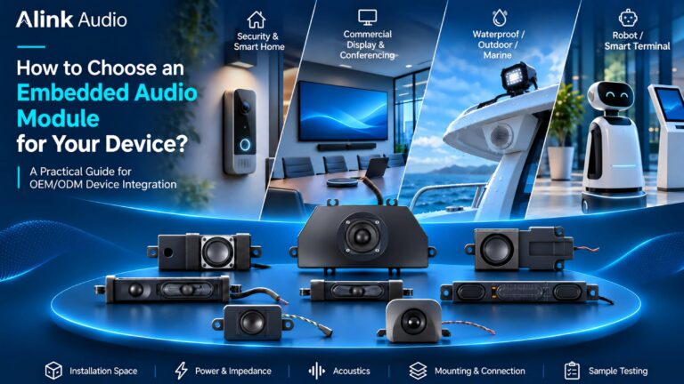

How can an embedded speaker module perform well during a laboratory evaluation but sound different after it is installed inside a security camera, commercial display, or smart terminal?
The answer often involves the complete device. Speaker placement, enclosure design, sound outlets, amplifier settings, and measurement conditions can all influence the acoustic result.
For OEM/ODM engineers, speaker module acoustic testing should therefore involve more than checking a frequency response curve or a single sound pressure level (SPL) value.
A useful evaluation process starts by defining the device’s acoustic requirements, reviewing the module’s reference data, and validating candidate modules under representative operating conditions.
If your project is still at the component selection stage, begin with our guide to choosing an embedded audio module. Once a module has been shortlisted, the following testing steps can help determine whether it is suitable for further integration.
1. What Should Engineers Define Before Acoustic Testing?
Before measuring a speaker module, engineers should establish what the finished device is expected to reproduce.
Different applications require different acoustic priorities.
For example, a security device may need clear voice prompts and alerts. A conferencing display may need intelligible speech over a wider listening area. A smart terminal may use short interactive responses, while outdoor equipment may need audible notifications in a noisy environment.
These differences affect the appropriate evaluation criteria.
Define the Intended Audio Application
Start by identifying:
- The main audio content, such as speech, alerts, or multimedia.
- Typical listening distance and direction.
- Expected background noise.
- Available amplifier and power supply.
- Speaker placement and sound outlet location.
- Mechanical and environmental constraints.
- Any project-specific acoustic acceptance requirements.
The purpose is not to create one universal pass/fail standard for every speaker module.
Instead, engineers should define measurable targets and evaluation conditions that reflect the intended device.
Why Does Listening Distance Matter?
Sound pressure measured close to a speaker is not necessarily representative of what a user hears farther away.
Distance, orientation, reflections, and nearby surfaces can affect the measured sound field.
For a voice prompt device, the relevant evaluation position may differ from that of a conference display.
Engineering Takeaway: Define the audio function and intended listening conditions before comparing acoustic measurements.
2. How Should Engineers Read a Speaker Frequency Response Curve?
A frequency response curve describes how a speaker’s measured acoustic output varies across frequency under specified test conditions.
It is one of the most useful references when evaluating an embedded speaker module.
However, a frequency response curve should not be interpreted without understanding how the measurement was performed.
What Do the Axes Show?
The horizontal axis normally represents frequency, measured in hertz (Hz).
The vertical axis represents an acoustic level, often in decibels (dB), according to the measurement and graph format.
Before comparing curves, check whether the level is presented as an absolute sound pressure level, a relative response, or another defined measurement.
What Should You Look for in the Curve?
Engineers may review:
- The frequency range relevant to the intended audio content.
- Broad response variations.
- Peaks or dips that may require investigation.
- Changes in response under different test conditions.
- Differences between the standalone module and the installed device.
A visually flatter curve is not automatically the best solution for every product.
For example, the frequency balance suitable for short voice notifications may differ from the target for multimedia playback.
The intended content and listening conditions should guide interpretation.
Why Are Measurement Conditions Important?
Frequency response measurements are influenced by microphone position, measurement distance, test environment, input signal, and signal processing.
Room reflections can introduce variations that are not caused solely by the speaker module.
Different measurement techniques may be appropriate depending on the device and evaluation objective.
For additional technical background, see Audio Precision’s guide to loudspeaker acoustic measurements.
Engineering Takeaway: Use the frequency response curve to understand acoustic behavior, but compare measurements only when the relevant test conditions are known.
3. What Does Sound Pressure Level Tell You About a Speaker Module?
Sound pressure level, or SPL, is commonly used to describe acoustic output.
It provides useful information when engineers need to determine whether a device can deliver an appropriate sound level at the intended listening position.
However, an SPL value is meaningful only when its measurement conditions are understood.
Can You Compare SPL Values from Two Different Suppliers?
Not reliably unless the measurements use comparable conditions.
Important details include:
- Input voltage or electrical drive conditions.
- Measurement distance.
- Measurement axis and microphone position.
- Test signal and frequency range.
- Measurement environment.
- Relevant processing or filtering.
A higher published SPL number does not automatically mean that one module will perform better in your finished product.
Is SPL the Same as Perceived Loudness?
No.
SPL is a physical measurement. Perceived loudness depends on several factors, including frequency content, duration, and listening conditions.
For speech applications, intelligibility may be more important than simply maximizing the measured sound level.
A loud output with poor speech clarity may not satisfy the actual product requirement.
How Should Engineers Evaluate Output Level?
Start with the required listening conditions and establish a suitable measurement method.
Then evaluate the module using the intended amplifier and representative device configuration.
If the product uses multiple operating levels, testing may need to cover more than one relevant setting.
Engineering Takeaway: Evaluate SPL in the context of the intended application and documented test conditions, rather than comparing isolated numbers.
4. How Should Distortion and Unwanted Noise Be Evaluated?
Frequency response and SPL do not describe every aspect of acoustic performance.
A speaker module may produce an acceptable output level while introducing unwanted distortion, buzzing, or mechanical vibration.
These effects can become more noticeable under certain operating conditions.
What Is Harmonic Distortion?
Harmonic distortion occurs when a system produces frequency components related to the input signal that were not present in the original signal.
Total harmonic distortion (THD) is one way of quantifying part of this behavior.
However, THD does not describe every audible defect, and results depend on the measurement method and operating level.
Engineers should interpret distortion data alongside other measurements and listening evaluations.
What Is Rub & Buzz?
Rub & buzz refers to unwanted noise that may result from mechanical or structural problems during speaker operation.
Possible causes include interference, loose parts, or other defects, depending on the speaker and assembly.
These problems may not be fully characterized by a basic frequency response curve.
Specialized measurements and listening checks can help identify abnormal behavior.
For an overview of available loudspeaker distortion and rub & buzz measurements, see KLIPPEL’s measurement resources.
Why Should Testing Include Different Operating Levels?
Some unwanted effects become more noticeable as drive conditions change.
Depending on the intended application, engineers may evaluate relevant low, typical, and higher operating levels while remaining within the documented limits of the components.
The purpose is to understand behavior across realistic use conditions, not to drive the speaker beyond its approved operating range.
Engineering Takeaway: Check distortion, abnormal mechanical noise, and relevant listening performance in addition to frequency response and SPL.
5. Why Does Acoustic Performance Change After Device Integration?
An embedded speaker module operates as part of a larger system.
The finished device includes a housing, mounting interface, sound outlet, grille, wiring, and surrounding components.
These elements can influence the acoustic response.
How Does the Sound Outlet Affect Performance?
A sound outlet that is restricted, misaligned, or covered by additional material may affect the sound reaching the listener.
For example, the device design may introduce:
- A grille with limited open area.
- Mesh or protective fabric.
- A narrow or offset sound channel.
- Nearby internal obstructions.
- Gaps around an intended acoustic interface.
- Structural surfaces capable of vibrating.
The actual effect depends on the complete design.
Engineers should therefore review the speaker’s acoustic path before finalizing the device enclosure.
Can Mounting Cause Unwanted Noise?
Potentially.
Poor fastening, contact with nearby components, or unsuitable structural interfaces can contribute to unwanted vibration or rattling.
A module that performs acceptably as a standalone assembly may behave differently once installed.
This is why mechanical integration and acoustic evaluation should be considered together.
Our speaker module integration checklist covers installation dimensions, mounting features, connectors, and device-level design considerations.
Should Engineers Test the Module Inside the Finished Device?
Yes.
Representative device testing helps identify interactions that may not appear during standalone module evaluation.
The final configuration should include the intended housing, sound outlet, mounting arrangement, amplifier, and relevant signal processing wherever practical.
Engineering Takeaway: Evaluate the speaker module and surrounding device structure as one acoustic system.
6. Which Acoustic Test Conditions Should Be Recorded?
Repeatable testing depends on consistent, documented conditions.
If the drive level, microphone position, test environment, or signal processing changes between tests, differences in the results may not be caused by the speaker module alone.
A useful acoustic evaluation record can include the following information.
| Test Parameter | Information to Record |
|---|---|
| Sample Identification | Module version, sample reference, and configuration |
| Electrical Drive | Amplifier, input level, supply voltage, and relevant settings |
| Test Signal | Signal type, frequency range, and operating level |
| Microphone Setup | Microphone identification, position, distance, and orientation |
| Test Environment | Measurement room, fixture, and relevant environmental conditions |
| Device Configuration | Standalone module or installed device, including enclosure details |
| Signal Processing | EQ, DSP, volume control, and other relevant audio settings |
| Measurement Results | Frequency response, SPL, distortion, and applicable noise checks |
| Evaluation Notes | Observed issues, deviations, and follow-up actions |
Not every project requires the same measurement equipment or test complexity.
The test plan should be selected according to the performance requirements, available equipment, and stage of development.
Why Is Documentation Important?
A measurement result without its conditions may be difficult to reproduce or compare.
Recording the test setup allows engineers to distinguish between changes in the module, changes in the device, and changes in the measurement process.
This is particularly important when several module candidates or engineering revisions are being evaluated.
Should Reference Curves Be Used as Final Acceptance Data?
Not automatically.
A supplier’s reference curve can support preliminary selection, but the project may require additional measurements using the customer’s intended configuration.
Any acceptance criteria should be agreed upon and evaluated under defined conditions.
Engineering Takeaway: Document the test configuration and evaluation criteria so results can be compared consistently across samples and design revisions.
7. How Should Engineers Validate Samples Before Production?
Sample testing should help determine whether the proposed module configuration meets the intended device requirements.
The process normally involves more than checking whether the speaker produces sound.
A structured evaluation can identify electrical, mechanical, and acoustic issues before a design is approved for production.
Step 1: Confirm the Sample Configuration
Record the module’s reference information, connection arrangement, mounting structure, and other relevant specifications.
Confirm that the sample matches the intended evaluation configuration.
Step 2: Verify Electrical Compatibility
Review the amplifier’s supported load, supply conditions, output configuration, and relevant operating limits.
For more information, see our speaker impedance and amplifier matching guide.
Step 3: Evaluate Acoustic Performance
Measure or assess the parameters relevant to the project.
These may include:
- Frequency response.
- Sound pressure level.
- Distortion.
- Buzzing or rattling.
- Speech intelligibility or other application-specific listening performance.
Step 4: Test the Integrated Device
Install the module in a representative enclosure with the intended mounting and sound outlet arrangement.
Repeat the relevant measurements and listening checks.
Compare the results with the agreed project requirements.
Step 5: Review Issues and Design Changes
If performance does not meet the project objectives, identify the potential source of the issue.
Possible areas for review include the module, amplifier, enclosure, sound outlet, mounting structure, or signal processing.
Changes should be assessed for technical feasibility and validated again as needed.
Step 6: Confirm the Production Evaluation Plan
Before production approval, agree on which characteristics need to be controlled and how they will be checked.
The relevant inspection or testing approach should reflect the approved design and project requirements.
A reference sample or agreed evaluation criteria may be useful for future comparisons, but these should be established through the project’s confirmation process rather than assumed.
Engineering Takeaway: Sample validation should establish whether the complete device meets its intended performance requirements under documented conditions.
Frequently Asked Questions
Is a Flat Frequency Response Curve Always Better?
Not necessarily. The appropriate frequency response depends on the intended audio content, acoustic design, and listening conditions. A curve should be interpreted in the context of the application.
Can I Compare Speaker SPL Values from Different Datasheets?
Only with care. Meaningful comparisons require an understanding of the input levels, measurement distances, frequency ranges, and other relevant test conditions.
Does a Higher SPL Value Mean Better Sound Quality?
No. Sound quality also depends on frequency response, distortion, unwanted noise, and the intended listening experience.
Can a Speaker Module Pass Laboratory Tests but Perform Poorly in the Final Device?
Yes. The finished housing, grille, mounting arrangement, amplifier settings, and acoustic openings may affect performance after integration.
Do I Need to Test Every Audio Module in the Final Device?
The appropriate evaluation scope depends on the project. Candidate configurations should be assessed under representative device conditions, with production checks defined according to agreed requirements.
Final Thoughts: Validate the Complete Audio Experience
Speaker module acoustic testing is most useful when it connects reference measurements with real device requirements.
Frequency response, SPL, distortion, and unwanted noise provide different types of information. None should be interpreted without considering the test conditions and intended application.
For OEM/ODM projects, a practical evaluation process begins with clear performance objectives, continues through documented sample testing, and includes validation in the intended device configuration.
At Alink Audio, we help product teams review embedded audio module requirements, discuss acoustic and mechanical integration considerations, and prepare for project-specific sample evaluation. By focusing on the complete device rather than isolated specification values, engineering discussions can support more informed decisions before production.